I’ve spent time over the years playing with various hobbyist electronics platforms, such as Arduino and NodeMCU (ESP 2866). Most of the time it’s just been working on a breadboard but now I am working on a project that needs to be very minimal (low power and cost). For this I’ve decided to skip an actual Arduino and go with a plain ATmega328p. For those that don’t know, many Arduino boards are powered by the (formerly Atmel) Microchip ATmega328p. The Arduino platform makes it easy to prototype but when designing your own circuit, it’s nice to have full control over all the ICs and components used, so you can optimize for whatever your project calls for.
In this post I’m going to go through a simple tutorial of how to make an LED blink with a plain ATmega328p. Also, as I don’t have an official AVR programmer, but I do have an FTDI FT232R based USB cable, we will use the FTDI bit banging support in avrdude.
Getting the chip
First, you’ll need to get the ATmega328p. You can probably find it on Amazon, but I purchased mine from Digi-Key, specifically this unit.
As we will be using avrdude to do the programming with an FTDI cable, it doesn’t really matter if your chip has an Arduino bootloader programmed or not. Also, in this tutorial we will be using the internal 8Mhz RC oscillator, so an external crystal isn’t required.
Installing tools
We are going to skip the Arduino IDE all together and instead just use command line, specifically we need the AVR toolchain (avr-gcc) and avrdude. I’m using a Mac so I’ll give instructions for that, but it should be easy enough to install if you have another platform as well.
Install Homebrew if you don’t already have it, see this page.
$ brew tap osx-cross/avr
$ brew install avr-gcc avrdude
Wire up the programmer
You will need a FT232R based USB cable for this part. Essentially what we are going to do is configure avrdude with a new programmer type that will work with the FT232R and pay atttention that we map the pins on the cable to the ATmega chip.
| FT232R pin | avrdude ftdi_syncbb pin |
|---|---|
| TXD | 0 |
| RXD | 1 |
| RTS | 2 |
| CTS | 3 |
| DTR | 4 |
| DSR | 5 |
| DCD | 6 |
| RI | 7 |
Open up the file /usr/local/etc/avrdude.conf and add the following block:
programmer
  id    = "ftdi232rl";
  type  = "ftdi_syncbb";
  reset = 0;
  sck   = 1;
  mosi  = 3;
  miso  = 2;
;
If you want, you can tweak the values for reset, sck, mosi, and miso, just know this means you’ll need to wire up your FTDI cable differently to the ATmega chip. The above configuration says the following about how the cable is wired:
- TXD -> RESET
- RXD -> SCK
- CTS -> MOSI
- RTS -> MISO
Now is where you’ll need to consult the ATmega datasheet and the one for your FTDI USB cable (for me, it is this one).
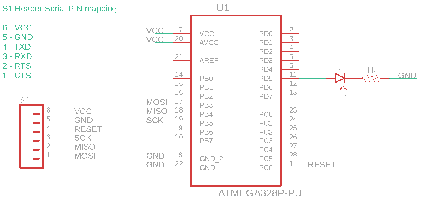
In addition to wiring the above to your ATmega, you’ll also need to wire up 2 VCC and 2 GND connections. You can use the VCC (5V in my case) and GND supplied by your FTDI USB cable to power the board.
Here is the full schematic:
Verify connectivity
Before starting, if you have previously installed the FTDI serial drivers (which you most likely have) for Mac OS, it will conflict with avrdude accessing the FTDI bit banging functionality. Run the following to check:
$ kextstat | grep FTDIUSB
If you see the FTDIUSB kext loaded, run the following to unload it (you can always manually kextload it back, or after restart it will auto-load):
$ sudo kextunload /Library/Extensions/FTDIUSBSerialDriver.kext
Now, run the following to see if avrdude can connect to your board:
$ avrdude -c ftdi232rl -p atmega328p -P ft0 -b 1200 -v
If all went well, you will see something like:
avrdude: AVR device initialized and ready to accept instructions

Reading | ################################################## | 100% 0.10s

avrdude: Device signature = 0x1e950f (probably m328p)
avrdude: safemode: hfuse reads as D9
avrdude: safemode: efuse reads as FF

avrdude: safemode: hfuse reads as D9
avrdude: safemode: efuse reads as FF
avrdude: safemode: Fuses OK (E:FF, H:D9, L:E2)

avrdude done.  Thank you.
NOTE: I use the -b 1200 argument above to use a slow baud rate. This is because my ATmega328p from the factory has a fuse set to divide the clock by 8 (CKDIV8).
If all is working, let’s update the low fuse (if necessary) to move up to an 8Mhz clock. (This isn’t necessary, but allows for faster programming). Check the calculator here to figure out the right fuse value, for me it is E2. Make sure to substitude your fuse value below where it says lfuse:w:0xe2:m.
$ avrdude -c ftdifriend -p atmega328p -P ft0 -b 240 -U lfuse:w:0xe2:m
If all goes well, let’s move on to building a program and flashing the MCU!
Blinking LED
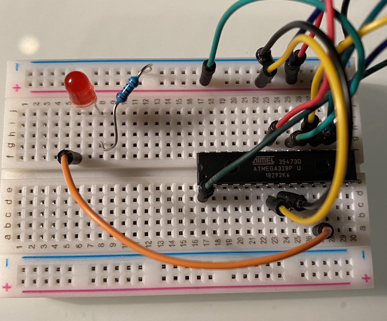
The blinking LED is one of the most basic examples, so it’s perfect for this. We will use pin PD5 to switch the LED on and off. Wire up PD5 to an LED and place a resistor in series after to ground. See the picture at the top of this post for an example. The code for this program is:
#include <avr/io.h>
#include <util/delay.h>

void main()
{
    while (1)
    {
        _delay_ms(1000);
        PORTD ^= 1 << PD5;
    }
}
To run this, I’ve uploaded the source code and a Makefile that handles compilation and flashing to your ATmega to GitHub here.
Locally, just run the following and it will compile and flash, and if everything is wired up correctly, you’ll see a blinking LED.
$ git clone https://github.com/chrismoos/avr-blinking-led
$ cd avr-blinking-led
$ make build flash